
With the servos, IMU, and GPS wired to the Beaglebone and ROS installed, it’s time to put the pieces together!
Servo Gyro Test
After installing ROS, I familiarized my self with the framework by writing some small tests. First I tried turning a servo using rotation, measured by a gyro. After several servo-abusing mistakes in my code, everything was up and running. There wasn’t any lag in my initial testing so I’m not quite sure what caused the stuttering that appears in parts of the video. Hopefully this doesn’t become an issue later on as I add more complexity.
The code consists of 2 ROSNodes. One to read and publish Z-axis rotatation rates and another to receive and integrate the rates into a relative angular position. The receiver node then turns the servo to that angle. Both nodes use the Adafruit BBIO library to interface with sensors and servos respectively. Both nodes for the test can be found in my Github.
The rate at which I retrieved gyro data was arbitrarily chosen, more testing is needed to determine an optimal rate that produces continuous, smooth readings and minimizes lag. Although gyroscopic drift is a well documented issue with rate gyroscopes like the ones in the MPU-6050, I am not concerned about its effects in this small scale test because this is more of a proof-of-concept. My later tests and final project will require a way to deal with the drift and cumulative measurement error.
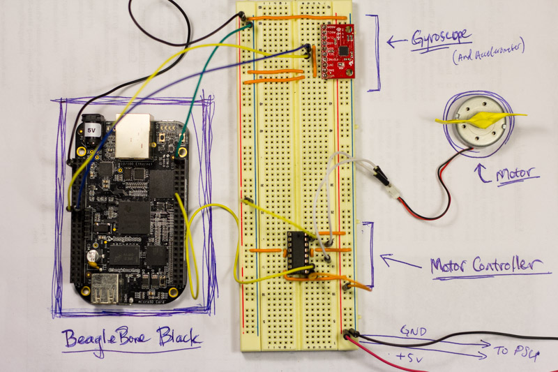
Motor Controller and Motor-Gyro Test
Driving the motor controller is surprisingly similar to the servo. For these simple motors, the only way to control the speed of an electric motor is by varying the voltage. This is pretty hard to do on its own. Instead I will use pulse width modulated signals, or PWM. By pulsing the power on and off faster than the motor can react, the PWM signals simulate a varying voltage source.
At first I was concerned that the TI SN754410 used 5v logic levels since the Beaglebone Black had 3v3 logic. But it turns out that 3v3 was designed to be partially backwards compatible with the greedier 5v. Since these logic levels are binary - that is, on or off - there is a threshold near the middle of the voltage range that determines a line’s on or off state. Thankfully the threshold is below 3v3 and thus, a 3v3 input is compatible with a 5v line.
WARNING: Just because 3v3 works with 5v inputs does NOT mean it works the other way. A 5v source can easily fry a 3v3 input. Look into a logic level converter if you come across this issue.
Even though the inputs connect to the Beaglebone’s 3v3 ports, VCC1 (logic power) still must be tied to 5v.
The Beaglebone, unlike an Arduino, does not have the power to run a motor. Thus, VCC2 - motor power supply - must use an external source. For testing, I used my lab bench power supply that made from an old computer PSU.
For this initial test, I only ran the motor one way. The rotation rates from the gyro control the PWM signal - and thus the speed - of the motor. To run the motor in both directions, there needs to be two PWM lines connected to the BBB. Somewhere in the code there will be a switch to change the active PWM line and tie the other line to ground.
Next Steps
Now with the parts working, I need to start installing them into the car and writing up more robust code (rather than just cobbling together examples). I also will need to start writing the fancy complex algorithms that actually navigate and drive the car. Finally, the electronics need to move from a breadboard to a perfboard on the car. I’ll also need to look into batteries.